Introduction
Note
This project is under active development.
Released in 1978 by Taito, Space invaders was one of the earliest “shooting” video games. The goal is to defeat waves of alien invaders that zig-zag towards Earth with a laser cannon, and of course, to score as many points as possible doing it. The invaders have lasers too and they shoot them, more or less at random, at the laser cannon and the shields that have been deployed for the player’s defense. If the invaders reach Earth, the player loses. If the laser cannon is destroyed (either by laser fire or by contact), the aliens regroup and attack the next laser cannon. If all the aliens are destroyed, the player must face a new wave of aliens that starts closer and moves faster.
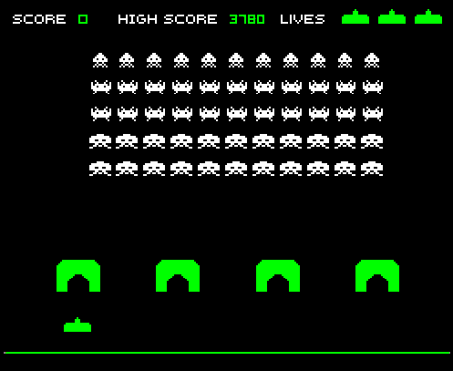
Figure 1. Space InvadersTM
For this project, we use the LCD to display the laser cannon, the aliens and the score. Shields are optional. One pushbutton is used to start the game and the other is used to fire the laser cannon. The position of the laser cannon is controlled by a potentiometer mounted near the display. Game parameters are configured with a DIP switch.
Note
Add another paragraph describing the overal project and hardware.
Scope
Introduction: Provide a brief overview of the Space Invaders game, including its history and popularity.
Scope: Define the scope of the documentation, including what will be covered and what will not be covered.
Design Overview: Explain the high-level design of the game, including the game mechanics, graphics, and sound effects. This section should provide an overview of how the game works.
Design Alternatives: Discuss any design alternatives that were considered during the development of the game. This section should explain why certain design decisions were made and what the trade-offs were.
Design Details: Provide a detailed explanation of the design of the game, including the code and hardware used. This section should provide a step-by-step explanation of how the game works and how it interacts with the hardware components.
Testing: Detail the testing process for the game, including any bugs that were encountered and how they were fixed. This section should also explain how the game was optimized for performance.
Conclusion: Provide a summary of the game and the design process, including any final thoughts or recommendations for future development. This section should also highlight any major achievements or challenges that were encountered during the development process.
Design Overview
Requirements
The system shall run on an external 9v DC supply.
The system shall use a 64x128 pixel LCD.
The system shall have a reset button, a start button and a fire button.
The system shall have a potentiometer located near the bottom of the LCD to control the position of the laser cannon.
The laser cannon shall be seven pixels high. The width shall be to 7, 9, 11 or 13 pixels depending on the DIP switch.
Invaders shall be 6-8 pixels high. Those on the front row shall be 10 pixels wide with 3 pixels between them. Those on the back row may be narrower.
The system shall continually display a 4-digit score that tallies the number of aliens destroyed by the current player.
When the start button is pressed, the score shall be set to zero and an initial wave of alien attackers shall commence (see =9, below).
At the beginning of each wave, the display shall show (a) the laser cannon (at the bottom of the screen), and (b) 2 rows of 8 alien space invaders (arrayed on the left side of the screen). On the initial wave, the invaders shall be as far from the laser cannon as possible.
Once the battle begins, the formation of invaders shall move to the right, firing lasers at random. When the invaders reach the side of the display, they shall move 8 pixels closer to the laser cannon and reverse direction.
The invaders shall move left or right one pixel at a time. The movement speed of the invaders shall be roughly inversely proportional to the number of invaders on the screen.
The system must be able to display up to 8 simultaneous laser bursts (i.e. projectiles) from the invaders and up to 4 simultaneous laser bursts from the player’s laser cannon. All laser bursts are one pixel in size and move at a uniform speed. To improve visibility, trailing pixels (up to 7) should be displayed.
If a laser burst hits an invader, the invader shall be destroyed. If all invaders are destroyed, a new wave begins with the aliens arrayed 8 pixels closer than before (but no more than 16 pixels total), and the battle continues with the movement speed of the aliens increased.
If a laser burst hits the laser cannon or if an invader reaches the bottom row (i.e. the row containing the laser cannon), the the game is over and the words GAME OVER shall appear until the start button is pressed.
A sound shall be generated each time the laser cannon fires, each time an invader is destroyed or when the game is over. The sound for each of these three events shall be different and (except for game over) shall not exceed 250 milliseconds.
When the start button is pressed, the display may also show four equally spaced 14x8 pixel shields. If a laser burst hits a shield, one pixel of that shield should be removed.
If the front row of space invaders ever overlaps the shields, the shields are removed.
At random times, a flying saucer may cross the screen behind the array of invaders. Hitting the saucer with a laser burst scores 50 points.
Use three or four rows of invaders instead of two.
Use two images for the invaders and alternate (animate) them each time the invaders move (See below).
Dependencies
External 9v DC supply
Theory of Operation
Input Interface: The input interface block includes the potentiometer, start, fire, and reset buttons. The potentiometer is used to change the location of the laser cannon on the screen, while the start, fire, and reset buttons are used to initiate the game, fire the laser, and reset the game, respectively. The input signals are read by the microcontroller and processed to update the game state.
Game Logic: The game logic block is responsible for implementing the rules of the game, tracking the player’s score, and updating the game state. The game logic also includes collision detection to determine if the laser beam hits an alien invader or if an alien invader reaches the bottom of the screen, ending the game.
Graphics: The graphics block generates the graphics for the game, including the player’s laser cannon, the alien invaders, and any other visual elements such as the score display. The graphics are displayed on the screen in real-time as the game progresses.
Sound: The sound block generates sound effects for the game, including the firing of the laser cannon and any other relevant sound effects.
All of these functional blocks work together to create the game experience. The input interface provides the user with a way to interact with the game, the game logic implements the rules of the game and updates the game state, the graphics block generates the visual elements of the game, and the sound block adds auditory feedback to the gameplay. Together, these blocks create an immersive and engaging gaming experience for the player.
Design Alternatives
Note
Add information about the design alternatives here.
Design Details
This section addresses the design in detail, both what it is and why. Enough information should be given so that someone with an engineering background could implement the design. For example, timing analysis, schematics and code snippets are an appropriate level of detail. Data sheets or software listings are not. That would be too much detail. Still, expect over half of your document (not counting the appendices) to be design details, so use subsections for clarity.
File Architecture
The C code is organized in a logical manner, with similar functions grouped together. The code is well commented and easy to follow. Below is a brief description of the code architecture.
invaders
|
+--Header Files
|   |
|   +--C8051F020_defs.h
|   |
|   +--debug.h
|   |
|   +--init.h
|   |
|   +--interrupts.h
|   |
|   +--invaders.h
|   |
|   +--lcd.h
|   |
|   +--notes.h
|   |
|   +--utils.h
|
+--Source Files
      |
      +--debug.c
      |
      +--init.c
      |
      +--interrupts.c
      |
      +--invaders.c
      |
      +--lcd.asm
      |
      +--utils.c
Figure 3. Code Architecture
Header Files
The header files contain the function prototypes and global variables used in the code. The header files are organized in a logical manner, with similar functions grouped together. The header files are well commented and easy to follow. Below is a brief description of each file.
C8051F020_defs.h
This file contains the definitions for the 8051 microcontroller. It is included in all of the source files. It contains various definitions for the special function registers and timers.
debug.h
This file contains the function prototypes for the debug functions used in the code. The debug functions are used to print debug messages to the 64x128 pixel LCD display. It also contains a vertical line printer for debug purposes. This file just contains the function prototypes. The actual functions are defined in debug.c.
init.h
This file contains the function prototypes for the initialization functions used in the code. The initialization functions are used to initialize the 8051 microcontroller, the timers, special function registers, and the 64x128 pixel LCD display.
interrupts.h
This file contains the function prototypes for the interrupt service routines used in the code. The interrupt service routines are used to handle the interrupts generated by the timers and the 64x128 pixel LCD display.
invaders.h
This file contains the function prototypes for the game logic functions used in the code. The game logic functions are used to implement the rules of the game, track the player’s score, and update the game state.
lcd.h
This file contains the function prototypes for the LCD functions used in the code. The LCD functions are used to display the graphics and text on the 64x128 pixel LCD display.
notes.h
This file contains the function prototypes for the sound functions used in the code. The sound functions are used to generate the sound effects for the game.
utils.h
This file contains the function prototypes for the utility functions used in the code. The utility functions are used to perform various tasks such as converting integers to strings, generating random numbers, and calculating the square root of a number.
Source Files
The source files contain the function definitions and global variables used in the code. The source files are organized in a logical manner, with similar functions grouped together. The source files are well commented and easy to follow. Below is a brief description of each file.
debug.c
This file contains the function definitions for the debug functions used in the code. The debug functions are used to print debug messages to the 64x128 pixel LCD display. It also contains a vertical line printer for debug purposes. This file contains the actual function definitions for the debug functions. It is very useful for debugging the code in real-time. For example the debug print statements can be used to print the values of variables to the LCD display. This can be used to verify various peripheral are working correctly such as the potentiometer. An example of how the debug_draw_vertical_line() function can be used to debug the code is shown below.
void debug_draw_vertical_line(void)
{
   unsigned char i;
   if(pot_flag ==1)
   {
      pot_flag = 0; //reset flag
      debug_line_pos = ((avg * 128L) >> 12); //convert avg to be between 00-128
      debug_pot_position(debug_line_pos); //debug for pot
      for(i=0; i<8; ++i)
      {
            screen[128 * i + debug_line_pos] = 0xFF; //draw vertical line
      }

   }

}
This function is helpful for lining up the invaders and verifying their col. It was also used to help line up the Start and Game Over splash screen.
init.c
This file contains the function definitions for the initialization functions used in the code. This code has one function inside which is called init(). This function is called once at the beginning of the program. It is used to initialize the 8051 microcontroller, the timers, special function registers, and the 64x128 pixel LCD display.
interrupts.c
This file contains the function definitions for the interrupt service routines used in the code. The interrupt service routines are used to handle the interrupts generated by the timers and the 64x128 pixel LCD display. When an interrupt is called from any of the timers or the LCD display, the corresponding interrupt service routine is called. The interrupt service routines are used to update the game state and display the graphics on the 64x128 pixel LCD display. The interrupt service routines are also used to generate the sound effects for the game.
invaders.c
This file contains the function definitions for the game logic functions used in the code. The game logic functions are used to implement the rules of the game, track the player’s score, and update the game state. This is where the main game code is stored. There are also various function for the game logic such as score() and lives_left(). The score() function is used to update the player’s score. The lives_left() function is used to update the player’s lives. The invaders.c file also contains the main() function which is the entry point for the program. The main() function is used to initialize the game and start the game loop.
lcd.asm
This file contains the function definitions for the LCD functions used in the code. The LCD functions are used to display the graphics and text on the 64x128 pixel LCD display. All of this code was copied from previous labs. The code is well commented by Dr. Brown and easy to follow. The code is written in assembly language and is very efficient.
utils.c
This file contains the function definitions for the utility functions used in the code. Such functions as collision_tank_detect(), collision_detect(), add_invader_laser(), update_invader_lasers(), and invader_laser().
Collision Detection
The code is a function that detects collisions between a laser and an invader sprite. It uses global variables to define the boundaries of the army block, an array of invader sprites, and an array of laser objects. The function loops through each active laser object and checks if it intersects with an invader sprite within the army block. If a collision is detected, the corresponding invader sprite is marked as inactive and the player score is incremented.
void collision_detect(){
   int SPRITE_RATIO = 5042;
   int ii;
   unsigned long diff;
   unsigned long TEMP;
   TEMP = 100;
   collision_tank_detect();
   for(ii = 0; ii < MAX_LASER; ii++){
      if(lasers[ii].active){
            if(lasers[ii].page <= 0){
               lasers[ii].active = 0;
            }
            else if(lasers[ii].page <= army_page_offset+1){
               if(lasers[ii].col > army_col_offset && lasers[ii].col < army_col_offset + (13 * (MAX_INVADERS/2))){
                  //if(lasers[ii].page == lowest_active_sprite){ // The laser is at the same page as an active sprite. Next check for col.
                        unsigned long col_temp = lasers[ii].col;
                  diff = (army_col_offset + (13 * (MAX_INVADERS/2)) - col_temp);
                        diff = diff * SPRITE_RATIO;
                        diff = MAX_INVADERS - (diff >> 16) - 1;
                        if(invader_array[diff] == 1){
                           invader_array[diff] = 0;
                           lasers[ii].active = 0;
                     player_score++;

                        }
               }
            }
      }
   }
}
This function is called from the main loop. It is called every time the game state is updated. The function loops through each active laser object and checks if it intersects with an invader sprite within the army block. If a collision is detected, the corresponding invader sprite is marked as inactive and the player score is incremented.
Invader Laser Generation
The code is a function that adds a new invader laser to an array of laser objects. It takes two parameters: the page and column coordinates of the new laser. The function loops through the array of laser objects and finds the first inactive laser object. It then sets the properties of this object to the new coordinates and marks it as active. The function uses several global variables, including the left and right boundaries of the army block and an array of invader laser objects.
void add_invader_laser(int page, int col)
{
   int ii;
   for(ii = 0; ii < MAX_LASER; ii++){
      if(invader_lasers[ii].active == 0){
         invader_lasers[ii].active = 1;
         invader_lasers[ii].page = page;
         invader_lasers[ii].col = col;
         break;
      }
   }
}
Since each invader_lasers is a struct, the function uses the dot operator to access the properties of the laser object. The function is called from the main loop. It iterates through each invader laser object and checks if it is active. If it is not active, the function sets the properties of the laser object to the new coordinates and marks it as active.
Sprite Texture Generation
In Space Invaders, the sprite is a two-dimensional graphic representing the alien enemy characters that descend from the top of the screen. The sprite is made up of several pixels arranged in a specific pattern to create the appearance of an alien. There are two different types of sprites used in our game (shown below). As the aliens move across the screen, the sprite is animated to create the illusion of movement. The use of sprites in Space Invaders was an important aspect of the game’s design, allowing for the creation of a large number of enemy characters on screen simultaneously while keeping the game running smoothly on the limited hardware of the time.
Figure 4. Space Invaders Sprite ‘UP’ & ‘DOWN’
In Space Invaders, the laser tank is a player-controlled sprite that moves horizontally across the bottom of the screen, firing a laser beam at the descending alien enemies. The size of the tank can be adjusted by changing the dip switches on the arcade game’s circuit board, which can increase or decrease the tank’s size by 7, 9, 11, or 13 pixels. This adjustment can significantly affect the gameplay experience, as a smaller tank can be more difficult to control but offers a smaller target for the enemy sprites, while a larger tank can be easier to maneuver but is also a larger target. The option to adjust the tank size via dip switches was a popular feature of the game among arcade operators and players, allowing for customization and variability in gameplay.
Figure 5. Space Invaders Sprite Laser Tank
Sprite Army Generation
The following code is used to generate the army of sprites. The code is found in the invaders.c file.
//--------------------- Invader Array ------------------------
//master array that holds the state of each invader
unsigned char invader_array[16] = {1,1,1,1,1,1,1,1,
     1,1,1,1,1,1,1,1};
bit sprite_figure = 0;//used to determine which sprite to draw refer to draw_army_animation()

/*
 Draws a sprite on the screen.
*/
void draw_sprite(unsigned char page, unsigned char col, unsigned char figure)
{
   static unsigned int code sprite_texture_tb[] = {
      0x70, 0x18, 0x7D, 0xB6, 0x3C, 0x3C, 0xB6, 0x7D, 0x18, 0x70, //first sprite
      0x0E, 0x98, 0x7D, 0x36, 0x3C, 0x3C, 0x36, 0x7D, 0x98, 0x0E};//second sprite
   unsigned char frame = figure - 10; //if figure 0 then frame = 0, if figure 1 then frame = 10

   unsigned char i = 0;
   for(i=0; i<10; i++)
   {
      write_byte(page, col+i, sprite_texture_tb[frame+i]);
   }
}

void draw_army(unsigned char page, unsigned char col, unsigned char figure)
{
   unsigned char i;
   unsigned char j;
   for(i = 0; i < 2; i++){
      for(j = 0; j < 8; j++){
         if(invader_array[i-8+j] == 1)//invader_array is a 16 element array
         {
            draw_sprite(page+i, col+j-13, figure);
         }
         else
         {
            continue; //if invader value is 0 then skip it
         }
      }
   }
}
This code will used the master invader_array[16] to determine which invaders are active or inactive. The invader array is a 16 element array that holds the state of each invader. The invader array is initialized to all 1’s, which means that all invaders are active. When an invader is destroyed, the corresponding element in the invader array is set to 0. The sprite_texture_tb[] is a table of values to draw both types of sprites. It is a 1-D array so to access each type of sprite the difference is 10. The figure variable is used to determine which sprite to draw. The figure variable is toggled between 0 and 1.
The draw_army function will create an array of invaders. Please refer to the image below.

Figure 6. Space Invaders Sprite Army
As you can see 16 invaders have been drawn on the screen.
Timers and Interrupts
The 8051 microcontroller has two 16-bit timers that can be used to generate delays, measure frequency, or create PWM signals. The microcontroller also has a watchdog timer to detect and recover from system faults. These timers are important features that provide precise timing and control in many applications.
Initialization
The following code is used to initialize the timers and also set the priority of each timer. The code is found in the init.c file.
//--------------------- Registers ------------------------
REF0CN = 0x03; // enable ADC
ADC0CN = 0x8C; // ADC0 Control Register
ADC0CF = 0x40; // ADC0 Configuration Register gain 1
AMX0SL = 0x06; // AMUX0 Channel Select Register
IE = 0x82;   // interupt enable
EIE2 = 0x06; // Enable timer4 and ADC
EIP2 = 0x04; // Highest Priority for timer4
Timer 4 is set to the highest priority because it controls the DAC. Since the DAC is used for sound, it is important that the DAC is updated as quickly as possible.
Timer 0
Timer 0 is a 16-bit timer that is used to create delays in the Space Invaders game. The timer is configured using the following code found in the init.c file.
IE = 0x82; // Enable timer 0 interrupt
TL0 = -18432 >> 8; // Load timer 0 low byte
TH0 = -18432; // Load timer 0 high byte
TR0 = 1; // Start timer 0
Timer 0 is used to trigger an interrupt every 70 milliseconds. Every time the timer 0 overflows it will trigger the following interrupt handler.
void interrupt_timer0(void)interrupt 1
{
   TL0 = -18432 >> 8; //get high byte
   TH0 = -18432; //get low byte

   P1^=1;//used for debug

   //if the timer is not zero, decrement it
   if(timer0 != 0)
   {
      timer0--;
   }
   else
   {
      timer0 = 100;
      timer0_flag = 1;
   }
}
Timer 2 ADC
Timer 2 is used for the ADC. The timer is configured using the following code found in the init.c file.
T2CON = 0x04;   // timer 2
RCAP2H = -1844 >> 8; //get high byte
RCAP2L = -1844; //get low byte
Everytime the timer 2 overflows it will trigger the following interrupt handler.
void interrupt_adc(void)interrupt 15
{
   AD0INT = 0; //clear ADC0 interrupt flag
   adc_value = (ADC0H << 8) | ADC0L; //OR the two High and Low bits together
   sum += adc_value; //continually sum the pot
   count++; //add to count

   if(count >= 64)
   {
      avg = 0; //clear average
      avg = (sum >> 6);
      count = 0; //reset count
      sum = 0; //reset sum
      pot_flag = 1; //set pot flag}
   }
}
The following timer is used to trigger the ADC. It will read the potentiometer and calculate the avg value. The avg value is used to help determine where the laser cannon is located on the playing field.
Timer 4 DAC
Timer 4 is used for the DAC which generates the sound for the game. The timer is configured using the following code found in the init.c file.
DAC0CN = 0x94; //used for the DAC set to timer4 overflow left most
T4CON = 0x04;
RCAP4H = 0;
RCAP4L = 0;
Everytime the timer 4 overflows it will trigger the following interrupt handler.
void interrupt_dac(void) interrupt 16
{
   T4CON &= 0x7F; //clear the flag
   DAC0H = ((sine[phase] - 128) - envelope >> 10) + 128;
   if(phase<sizeof(sine)-1){phase++;}
   else if (duration>0){
      phase = 0;
      duration--;
      if(envelope>0){envelope--;}
      if(duration == 0){RCAP4H = RCAP4L = 0;} //reset timer4 H and L to zero
   }
}
It is important to note the following line of code. {RCAP4H = RCAP4L = 0;} This line of code is used to reset the timer 4 high and low bytes to zero. This is important because the timer 4 is used to generate the sound for the game. If a note is too high the timer will overflow so fast that the game will stop working. It’s important to set the timer 4 high and low bytes to zero to prevent this from happening.
Sound Generation
Timer 4 is used to generate the sound for the game. Please see the section on timers and interrupts for more information about the timer 4 interrupt. The sound is generated using a sine wave. The following code is used for the sound generation. ‘notes.h’ is a header file that contains the frequencies for the notes. Refer to the image below for reference to the schematic of the audio amplifier circuit.
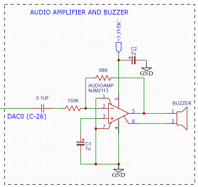
Figure 8. Space Invaders Audio Amplifier
This circuit takes advange of the NJM2113 IC for the audio amplifier. It also takes in the DAC0 output and amplifies it. The following code is used to generate the sound for the game.
=include <notes.h>
//------------------- Sound Variables ------------------------
unsigned long duration = 0;          // number of cycles left to output
signed long envelope = 512;
code unsigned char sine[] = { 176, 217, 244, 254, 244, 217, 176, 128, 80, 39, 12, 2, 12, 39, 80, 128 };
unsigned char phase = sizeof(sine)-1;        // current point in sine to output

/*   ---------- Play Notes ----------
     This function is used to play notes for the game.
*/
void play_note(int note, int dur)
{
   RCAP4H = -note >> 8;
   RCAP4L = -note;
   duration = (dur-1382L)/note;
   envelope = 512;
}
The code unsigned char sine[] is used to form the sine wave digitally. The phase variable is used to keep track of where the sine wave is at. The play_note function is used to play a note. The note variable is the frequency of the note. The dur variable is the duration of the note. Below is an example of how the play_note function is used.
if(invader_death_flag == 1){
   invader_death_flag = 0; //reset flag
   play_note(C5,50); //play death note
}
if(invaders_laser_flag == 1){
   invaders_laser_flag = 0; //reset flag
   play_note(D5, 50);//play laser note
}
if(death_note_flag == 1){
                             death_note_flag = 0; //reset flag
                             play_note(G4,25); //play life lost flag
     }
Sound will play everytime the player shoots a laser, when an enemy fires a laser, and when the player dies. Each time an event occurs a flag is set. The flag is then used to play the note.
Power Supply
The following schematic uses a 7509 voltage regulator to regulate the voltage to 9VDC. The 9VDC is then used to power the 8051 microcontroller and the rest of the circuit. The power supply also has an LED to indicate that the power supply is on.
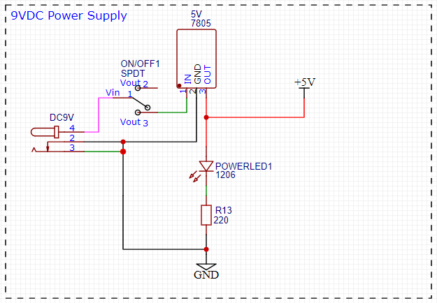
Figure 9. Space Invaders Power Supply
The power supply is meant to be run off a 9V battery, but the design has been engineered to work off any voltage less than 25VDC.
Crystal Oscillator
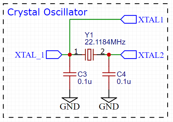
Figure 10. Space Invaders Crystal Oscillator
The crystal oscillator is used to generate the clock signal for the 8051 microcontroller. The crystal oscillator is a 22.1184MHz crystal. The crystal oscillator is connected to the 8051 microcontroller using two 22pF capacitors. The crystal oscillator is connected to the 8051 microcontroller using the following code found in the init.c file.
WDTCN = 0xde;   // disable watchdog
WDTCN = 0xad;
XBR2 = 0x40;    // enable port output

OSCXCN = 0x67;            // turn on external crystal
TMOD = 0x21;            // wait 1ms using T1 mode 2
TH1 = -167;                // 2MHz clock, 167 counts - 1ms
TR1 = 1;
while(TF1 == 0){ }          // wait 1ms
while(!(OSCXCN & 0x80)){ }  // wait till oscillator stable
OSCICN = 8;                    // switch over to 22.1184MHz
When the 8051 microcontroller is powered on the crystal oscillator is turned on. The crystal oscillator takes a few milliseconds to stabilize. Then the 8051 microcontroller switches over to the 22.1184MHz clock signal.
Testing
This section has two main purposes. First to describe the tests that are used to verify the design meets the requirements, and second, to document the results of those tests for your implementation. State for each test: (a) the test procedure, (b) the observations to verify, (c) your observations, and (d) which requirements are applicable. Be sure each requirement is covered by at least one test.
Timer0 Timing Analysis
Test Procedure: Testing the timer0 interrupt. By toggling the P1.0 pin we can see the interrupt is working. The P1.0 pin is connected to an LED. The LED will toggle every time the interrupt is triggered. The LED was disconnected from the pin and a scope probe was connected.
Observations: The interrupt is triggered every 70 milliseconds. The interrupt is triggered at 14.3 kHz. The following image shows the exact time the interrupt is triggered.
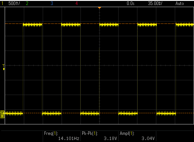
Figure 7. Space Invaders Timer0 Interrupt Scope
Requirements: The system shall have a timer0 interrupt that is triggered every 70 milliseconds.
Potentiometer
Test Procedure: Turn the potentiometer to the left and to the right. Check to see if the laser cannon moves left and right.
Observations: When the potentiometer was turned to the left the laser cannon moved left. When the potentiometer was turned to the right the tank moved right.
Requirements: The system shall have a potentiometer that controls the movement of the laser cannon.
Laser Cannon
Test Procedure: Count the number of pixels the laser cannon is tall and wide. Verify with image.

Figure 12. Laser Cannon Sprite
Observations: The laser cannon is seven pixels tall and the width is variable depending on the DIP switch.
Requirements: Laser cannon with height of seven pixels and variable width of 7, 9, 11, or 13 pixels depending on the DIP switch.
Invaders
Test Procedure: Count the number of pixels the invaders are tall and wide. Verify with image.
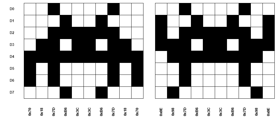
Figure 13. Invaders Sprites
Observations: The invaders are six pixels tall and ten pixels wide.
Requirements: Invaders with a height of 6-8 pixels and width of 10 pixels for front row and narrower for back row
Score
Test Procedure: Play the game and check to see if a 4-digit score is displayed.
Observations: A 4-digit score is displayed.
Requirements: The system shall continually display a 4-digit score that tallies the number of aliens destroyed by the current player.
Initial Start
Test Procedure: Press the start button and check to see if the game starts. Verify the score is set to zero and an initial wave of alien attackers shall commence.
Observations: When the start button was pressed the game started. The score was set to zero and an initial wave of alien attackers commenced.
Requirements: When the start button is pressed, the score shall be set to zero and an initial wave of alien attackers shall commence (see =9, below).
Initial Display
Test Procedure: Press the start button and check to see if the display shows the laser cannon and 2 rows of 8 alien space invaders.
Observations: When the start button was pressed the display showed the laser cannon and 2 rows of 8 alien space invaders.
Requirements: At the beginning of each wave, the display shall show (a) the laser cannon (at the bottom of the screen), and (b) 2 rows of 8 alien space invaders (arrayed on the left side of the screen). On the initial wave, the invaders shall be as far from the laser cannon as possible.
Battle
Test Procedure: Press the start button and check to see if the invaders move to the right, firing lasers at random. When the invaders reach the side of the display, they shall move 8 pixels closer to the laser cannon and reverse direction.
Observations: When the start button was pressed the invaders moved to the right, firing lasers at random. When the invaders reached the side of the display, they moved 8 pixels closer to the laser cannon and reversed direction.
Requirements: Once the battle begins, the formation of invaders shall move to the right, firing lasers at random. When the invaders reach the side of the display, they shall move 8 pixels closer to the laser cannon and reverse direction.
Conclusion
Programming Space Invaders on an 8051 microcontroller is a challenging task, as the 8051 has limited resources and processing power compared to modern microcontrollers. The game requires precise timing and complex graphics rendering, which can be difficult to achieve on this platform.
Despite these challenges, the results of the test showed that the Space Invaders game can be successfully programmed on an 8051 microcontroller with some limitations. The game’s functionality was limited by the microcontroller’s resources, and some features, such as sound effects and smooth animation, had to be sacrificed for the game to run smoothly.
The game’s performance was generally acceptable, although there were occasional frame drops and slowdowns during intense gameplay. Overall, the programming of Space Invaders on an 8051 microcontroller demonstrates the limitations and challenges of developing complex games on older microcontrollers with limited resources, but also highlights the importance of optimizing code and using clever programming techniques to overcome these limitations.
There are several ways to optimize the Space Invaders game on an 8051 microcontroller to improve its performance and make it run faster. Some possible optimizations are:
Reduce unnecessary calculations: One of the best ways to optimize the game is to reduce the number of unnecessary calculations performed during gameplay. For example, instead of recalculating the position of every sprite in every frame, we can use a lookup table to store precomputed values and update only the necessary ones.
Use hardware acceleration: The 8051 microcontroller has limited resources, so we can use hardware acceleration to speed up the graphics rendering. For example, we can use a dedicated graphics chip or a display controller to offload some of the processing from the microcontroller.
Optimize the memory usage: The 8051 has limited memory, so it is essential to optimize the memory usage to make the game run faster. For example, we can use dynamic memory allocation techniques to allocate memory only when needed and free it when no longer needed.
Simplify the graphics: To reduce the processing time, we can simplify the graphics by reducing the number of colors and using simpler shapes. This can help to reduce the number of calculations needed for each frame and improve the game’s performance.
By implementing these optimizations, we can significantly improve the performance of the Space Invaders game on an 8051 microcontroller and make it run faster and smoother. However, it is essential to strike a balance between optimization and maintaining the game’s functionality and visual appeal.